WN Blog 010 – Cisco Catalyst 9800 – Configuration Guide (Basics & Central Switching)
11min read
Finding C9800 stuff hot and interesting? You’re not
alone out there! 🙂
After initial C9800 configuration (see this blog) and registering your first AP (our AireOS AP Join Blog is still applicable here) you’re pretty much ready to go! There are just some pre-reqs to consider before we can associate with our first C9800 BSSID.
Pre-reqs
C9800 is built, GUI and CLI access is working
AP is registered
AP mgmt. VLAN (VLAN 10 in this example) is operational, AP has connectivity with to at least the vWLC
VM mgmt. VLAN (VLAN 11 in this example) is operational, C9800 can communicate with the network
WiFi Users VLAN (VLAN 20 in this example) is operational and, since it’s central switching we talk about here, VLAN 20 is allowed on C9800-CL management trunk (Gi2 in this example), on Port Group on the vSwitch C9800 Gi2 is mapped to and on ESXi management trunk to the switch; VLAN 20 must be allowed across entire path from the C9800 to its gateway
Note: since we’re talking central switching mode here, authenticated WiFi users’ traffic will be dropped into WiFi users VLAN at the vWLC level!
Lab Environment
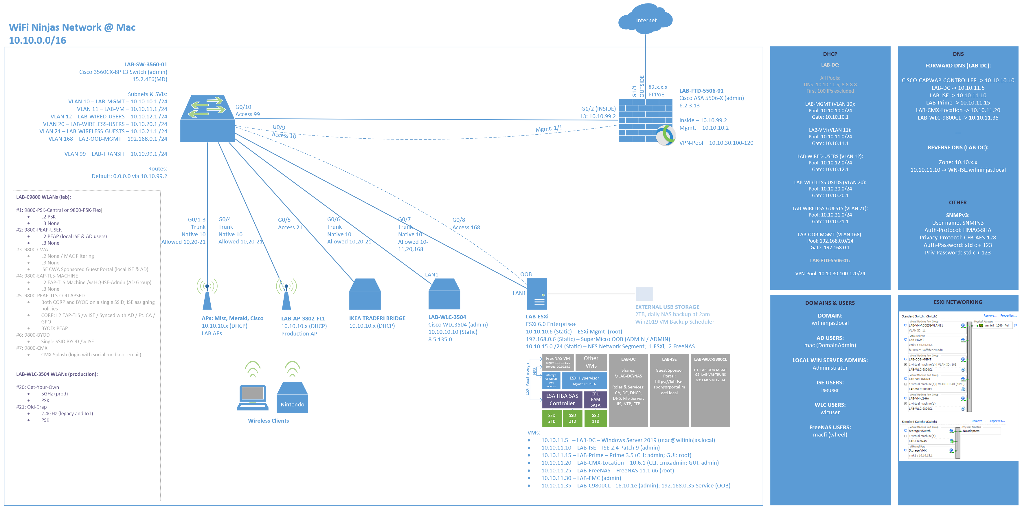
To get better picture, see my lab environment
below:
Lab Environment
New C9800 Architecture
Even though C9800 offers pretty much features
parity with our beloved AireOS WLC, it is slightly different. If you spent some
quality time with Cisco DNA Center you will feel comfortable with the new GUI
and structure. If not (like me), be prepared to change some old habits and
approach C9800 with an open mind 🙂
C9800 is designed to fit perfectly into Cisco SDA world and integration with DNAC and use of SGTs. But don’t worry if you don’t have few DNAC boxes worth £70k each and a fabric underlay lying around. C9800 can still work in a traditional way. The only real difference is where we configure the same stuff as we did in AireOS (using Profiles) and how we stich it together (using Tags).
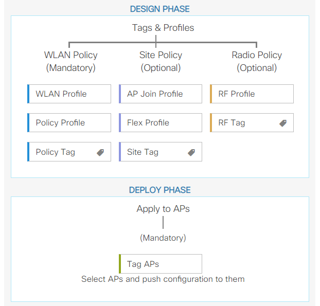
Look at the visual representation of major blocks
building a basic WiFi setup.
Wireless Setup Flow Overview
You can create multiple WLAN Profiles (SSIDs) and Policy Profiles and correlate both using a single Policy Tag. You then choose your AP Join Profile and Flex Profile (if in use) and correlate both using Site Tag. Your 2.4 and 5GHz RF profiles are stitched together using RF Tag. You now have all the config needed for the AP and SSID to operate described with just 3 tags, that are finally assigned to the AP of your choice. Takes some time getting used to, but it’s really not too bad.
Let’s dive straight in. Once we start looking at the real config it shouldn’t feel too overwhelming.
Note: only the WLAN Policy is mandatory but it is best practice to use all 3 policies and understand impact they all have on our wireless network.
Configuration
In this example we’ll configure simple WPA2-PSK WLAN and cover more interesting stuff like popular enterprise security approaches using EAP (PEAP, EAP-TLS, BYOD) in future blogs! Guest flow (CWA with ISE) already has its blog and you can find it here: https://wifininjas.net/index.php/2019/08/13/wn-blog-009-c9800-wlc-guest-mab-cwa-ise/ 🙂
Below steps show how to configure your first centrally switched WLAN. It’s PSK-based, but you can easily translate it to any other auth method. Have fun 🙂
1. Configure WLAN Profile
This is a pretty standard WLAN configuration that
we’re all familiar with. Quite a few boxes to tick, tons of possibilities,
standard Cisco overcomplication that feels like 1:1 port from the AireOS.
Simplifying opportunity missed. But let’s not digress!
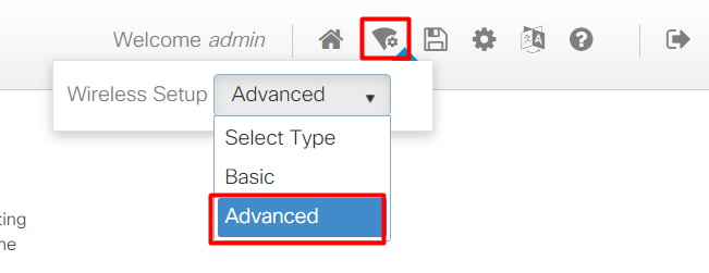
Go to Configuration > Tags & Profiles >
WLANs or (I like to do that), Advanced Wireless Setup
(top-right corner), where you can switch between all main solution building
blocks from one list.
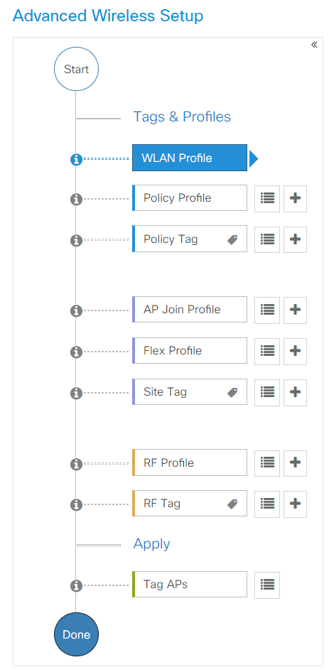
Advanced Wireless Setup
Amazing, isn’t it?
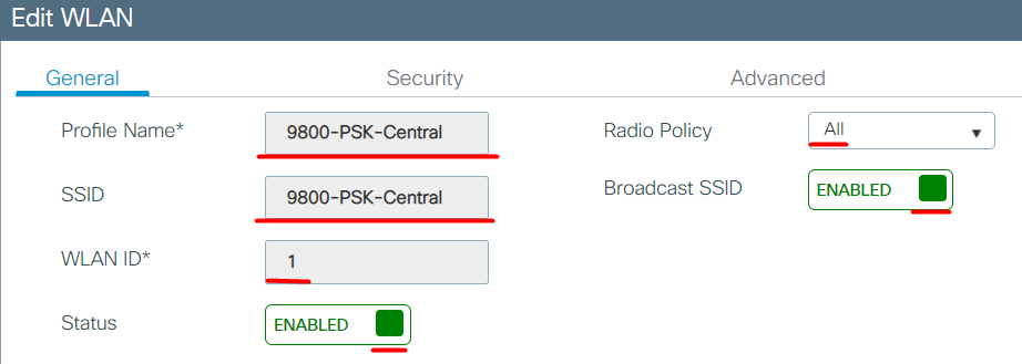
In General tab, configure Profile Name (must be unique) and SSID name (can have more than one on the same WLC) along with WLAN ID (ID <=16 = included in default Policy Profile, ID > 16 = won’t be included in default Policy Profile), Radio Policy (2.4GHz, 5GHz, or both). As L2 security in Security tab, use WPA + WPA2 with AES encryption and PSK key mgmt and specify ASCII PSK Key. FT should be disabled here due to Krack vulnerability. Leave all other security details on their default values. Advanced tab settings can also be left on default but please be mindful of the impact some settings on the performance and compatibility of your SSID. This is a topic for another discussion, but in essence I’d say that:
Aironet IE enables SSID name inclusion in beacons among many other things, which is helpful AF but can affect clients compatibility with this SSID
P2P Blocking is normally enabled on Guest SSIDs (blocks WiFi clients from attacking each other)
802.11v can seriously affect (positively or negatively) your roaming behaviour – test with your clients
802.11k is generally a good feature to use as it should reduce time your clients spend scanning off channel for alternative APs while roaming
Band select can be useful in some scenarios, but steer away when used with voice as it will make roaming slower
WLAN Profile General tab
WLAN Profile Security tab
2. Create a VLAN
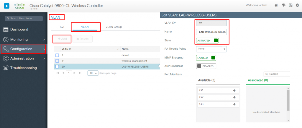
Since we’re dealing with central switching, we might think that we would need a dedicated SVI on the C9800 sitting in the VLAN into which we would like to drop authenticated users’ traffic in the same fasion as we did in AireOS. We could do it and it would work, but it’s not necessary here. All we need is to create VLANs (as opposed to SVIs) to get centrally switched WLANs to work.
Add VLAN in CLI ((config)#vlan [VLAN ID];
(config-vlan)#name [VLAN name]) or GUI in Configuration > Layer2 >
VLAN > Add
In this example I’m using VLAN 20 for wireless
users. L3 sits on my core switch. VLAN 20 is allowed on vSwitch and ESXi trunk.
Refer to the lab network diagram for more clarity – one pic speaks thousand
words.
Add VLAN for wireless users
3. Configure Policy Profile
This is where we can configure TrustSec, decide if
we want to use Central Switching, Authentication, DHCP or Association, map WLAN
to a VLAN, apply an ACL to an SSID, turn on RADIUS Profiling, specify QoS, AVC,
CAC, Anchors, AAA Policy (attributes returned to the NAC), basic WLAN timers
and many more. Sounds easy? I know, I too feel it’s slightly on the
overcomplicated side 🙂
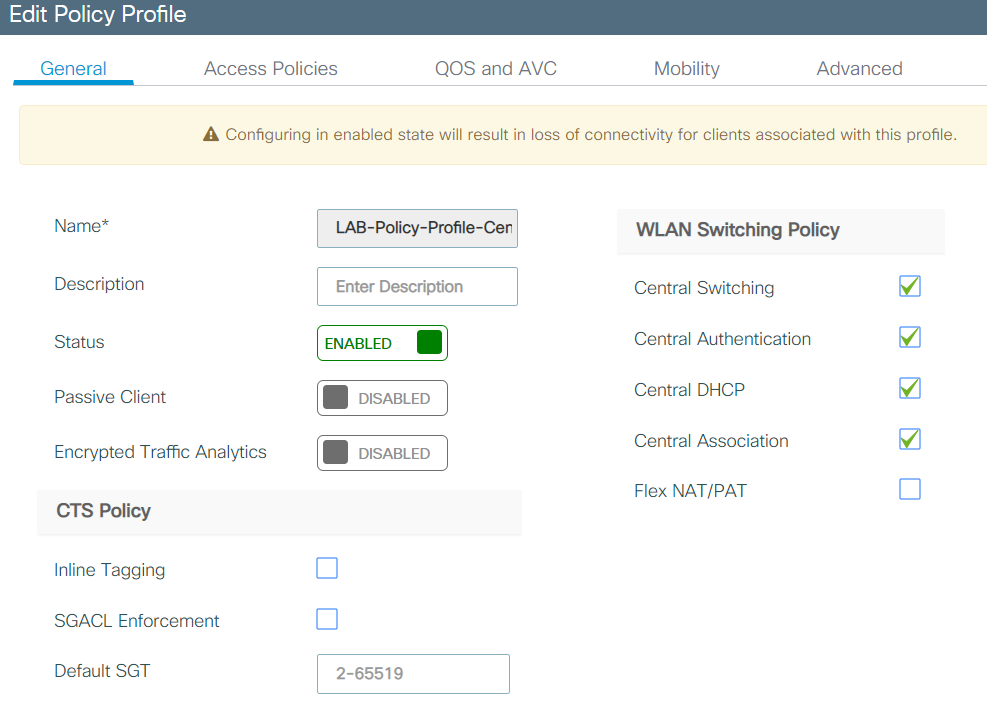
General Tab:
Policy Profile – General Tab
Minimum config required:
Specify Name
Set Status to
ENABLED
Enable Central
Switching and Central DHCP
If you want to know more:
WLAN Switching Policy
can move certain roles (switching, auth, DHCP, association) between AP and WLC.
Central everything is the default. Note that “Central DHCP” must be
used in Central Switching mode. If you disable it, clients won’t get an IP at
all. Authentication and Association roles can be moved between WLC and AP and
either would work just fine.
Passive Client (in
short) allow comms from wired devices to wireless devices with static IP
address by enabling WLC to pass ARP requests to them. Normally WLC proxies that
responses but since there is no DHCP used, WLC wouldn’t know about those
devices.
Access Policies Tab:
Policy Profile – Access Policies Tab
Minimum config required:
Specify VLAN/VLAN
Group assignment (use just a VLAN number or use VLAN name set in step 2.)
If you want to know more:
VLAN/VLAN Group is
where we specify the VLAN we want to drop wireless users into! This is
extremely important to understand, since we don’t assign WLANs to dynamic
interfaces (central) nor we have VLAN to WLAN mapping (flex) anymore. I have
assigned ‘LAB-WIRELESS-USERS’ VLAN 20, that I created in step 2.
WLAN ACL can be
applied to do basic firewalling on the AP or WLC level (depending if using
central switching or Flex) before the traffic even hits the firewall.
Let’s leave the rest on default for now. We’ll cover it in more details in future blogs.
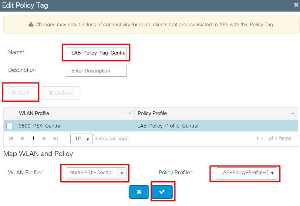
4. Configure Policy Tag
Policy tag just stitches WLAN Profile and Policy
Profile together, nothing else 🙂
We could mix and match different WLAN and Policy
Profiles while creating different tags. Example:
PSK WLAN with Policy
Profile on VLAN 20
EAP WLAN with Policy
Profile on VLAN 20
MAB WLAN with Policy
Profile on VLAN 666
You get the drill.
Policy Tag
Minimum config required:
Create a new Policy Tag and select WLAN and Policy Profiles created in previous steps
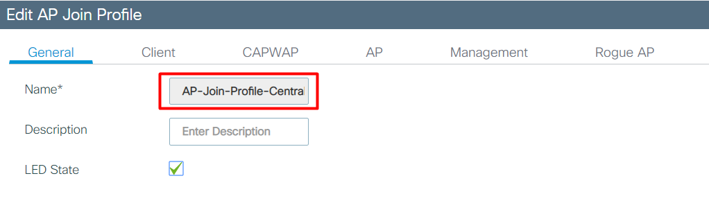
5. Configure AP Join Profile
Here we’ll configure basic parametres used by APs
after they join a controller.
AP Join Profile – General tab
Minimum config required:
Specify AP Join
Profile Name
If you want to know more (I’ll only mention stuff I
think is useful and filter out the noise):
If setting up a quick SSID is all we need, we can just create AP Join Profile, and specify its name in General tab. All other settings within the AP Join Profile can be left on default.
CAPWAP tab allows us to adjust CAPWAP & Retransmit timeouts and hardcode Primary and Secondary Controller Name and IP for N+1 designs.
AP tab allows us to set a Country Code, AP EAP Auth (FAST, PEAP, TLS), enable Hyperlocation, adjust BLE Beacons and AP Packet Capture settings (can capture straight to FTP location which is quite cool).
Management tab allows us to specify specific AP code that AP should download upon Joining the WLC, enable AP SSH access, set local mgmt user and dot1x credentials and set thresholds for detecting rogue APs.
Note: Flex Profile configuration is not required in Central Switching architecture.
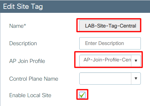
6. Configure Site Tag
Now, Site Tag is slightly special 🙂
You might expect that since Policy Tag was just
stitching profiles together, why would Site Tag be any different?
In Central Switching mode we don’t even specify Flex Profile assignment (let’s discuss it in more details in C9800 Flex blog post). We just specify Site Tag Name, AP Join Profile and, most importantly, we specify if the site is Local (centrally switched) or not (flex). It is confusing AF! In our example, we configure Site Tag with “Enable Local Site” checked.
Site Tag configuration
Minimum config required:
Set Site Tag Name,
specify AP Join Profile configured in previous step and check “Enable
Local Site” (which means that AP will leverage central switching).
7. Configure RF Profile
Custom RF Profiles are optional but extremely helpful to have, especially if your C9800 WLC caters for sites that have different RF requirement coverage areas. Maybe some sites will have APs expected to work in a High Density or Voice environment, while most APs would be serving ‘just data’ hungry stations? We would create different RF profile for each coverage type (High Density, Voice, Data) and for each band (2.4 and 5GHz).
Minimum config required:
None – custom RF
Profiles are optional
If you want to know more:
General tab is just for specifying Name, Band and Description. Make sure your RF Profile is Enabled.
802.11 tab is used to specify Data Rates and MCS Rates. Disabling low data rates is crucial in most scenarios (I personally never had to allow low data rates but I’ve heard stories where others had to due to weird wireless stations requirements). In short, management and control traffic is exchanged at lowest mandatory data rate. Clients associated with our BSSID would rate shift down when moving away from the AP and when the SNR drops for any reason. Supporting low rates and setting mandatory rate too low would contribute to sticky clients behaviour, slower transmission speeds for dodgy clients sitting on low data rates, increased airtime utililisation by those clients and finally, low mandatory rates would contribute to more airtime being consumed for control and management frames, leaving less space for data transmissions. Generally, in most situations, I would set minimum mandatory rate to 12 (standard deployment) or 24 Mbps (higher density), disable all lower rates and set all higher rates to supported. Please note that proper RF design following a proper on-site survey and predictive survey (and sometimes pre-deployment survey with AP-on-a-stick) is extremely important when tweaking radio configuration! Crap in crap out, can’t mitigate shit design with good config.
RRM tab is quite a comprehensive topic on its own! Let’s try to keep it short. You might want to increase default number of clients per AP that generate traps. Transmit Power Control (TPC) is extremely important to use wisely and to our advantage. Normally, it’s best to try and match Tx power level of the least powerful wireless device in the network. Allowing maximium available Tx power on the AP won’t necessarily mean ‘better coverage’. Coverage works in both directions – from AP and from a client. Not matching Tx power between AP and a client might cause asymmetric traffic patterns, where client can hear the AP, but AP can no longer hear the client. You also don’t want to go too low with Tx power as the goal is to maintain as high MCS rate as possible. Normally, 2.4GHz AP max Tx should be considerably lower than 5GHz max Tx. Dynamic Channel Assignment (DCA) is another supremely important factor contributing to general performance of a WiFi network. Do we want to bond channels? Do we want to use all available 5GHz channels there? The answer is “it depends”. I’d consider using 40MHz only in smaller deployments and only if it wouldn’t contribute to excessive channel contention. Remember that doubling the channel width doubles the interference and reduces SNR by 3dB. Also, even without ‘our’ APs, RF spectrum might already be crowded so we might want to stick to 20MHz sometimes even in smaller sites. Generally speaking it seems wise to stick to 20MHz in most cases in the enterprise world (but not only!) unless sheer higher throughout is required and you fully understand implications of bonding channels. Also, newer use “Best” channel width as we’ve seen it going wild with using 80MHz in central London on sites with 20+ CCI in a busy multi-tenant building. Now, which UNII bands to use? Stick to non-DFS channels 36-48? Use 36-64? Or maybe use all 19 available (in the EU) channels? It’s hard to answer this with a ‘one size fits all’ type of an answer, but in most cases we’d use all UNII bands, unless we have some weird clients that don’t work too well with upper bands and/or don’t support 802.11k while quick roaming is important.
Lastly, there are features like RX SOP or Client Load Balancing in the Advanced tab. RX SOP solves half of the CCI issue by ignoring signal below configured thershold from neighbouring BSSIDs operating on the same channel on an AP level. But how about contention on the wireless station level? Exactly. It’s still there. To solve this issue better, we’d want to think about 802.11ax, where OFDMA and BSS colouring should combat that contention crap nicely. Final tip – be careful with Client Load Balancing as it might hard disassociate your precious clients, potentially making them unhappy, especially if they’re in the middle of a call or conference. I now feel we should have a separate blog and podcast about the RF Profiles and RRM. And we probably will!
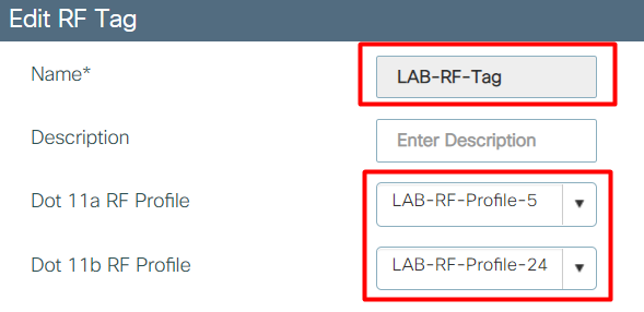
8. Configure RF Tag
We are almost there! With RF Profiles sorted, we
just need to stich 2.4 and 5GHz profiles together with an RF Tag.
RF Tag configuration
Using RF Profiles and RF Tags, again, is optional (but cool, so please use it).
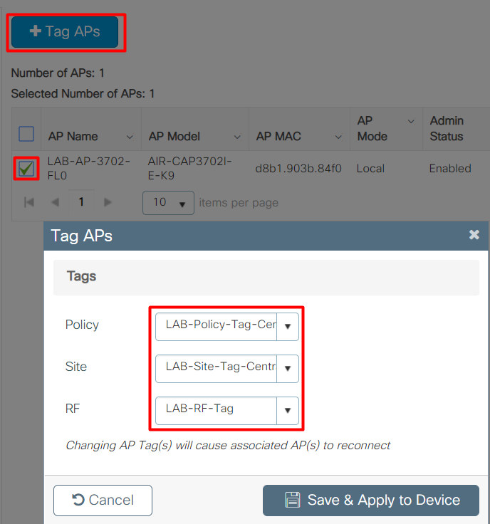
9. Apply Tags to the APs
Yup, this is the last step.
Select APs to tag and tag them with three tags we have created above (out of which only Policy Tag is mandatory).
Apply tags to APs
Think of tagging APs as of adding them to their relevant AP Groups with specific WLANs and RF Profiles. Well, kind of 🙂
That’s it. Simple. Similar to the AireOS that we all know and love so much, isn’t it? 🙂
Thanks for surviving going through this lengthy post and see you in the next WiFi Ninjas Blog!
Share blog
Share on facebook
Share on twitter
Share on linkedin
Share on email
Blog
This WiFi Ninjas Blog archive consists of all the blogs we have ever written!